Subscriber Autonomous System.
From a technological point of view, the Autonomous System-based solutions are simple and reliable, and the standardized configuration allows to implement any requirements of the corporate customer.
Each subscriber terminal in the standard configuration is capable of:
simultaneously work with several independent Internet channels in summation mode, redundancy (hot and cold) while transmitting six independent L2 channels, and the resulting L2 Ethernet transport can transmit packets both with and without VLAN 802.1Q technology (single TAG, QinQ). Read more here: https://www.mstnt.com/use-of-bandwidth/
(in other words: each subscriber terminal in a standard configuration, is capable of connecting six independent L2 links between terminals, it’s a patchcord between users’ computers, with all the advantages of a local network… no loss, packet sequence recovery, etc. regardless of their location).

Customer technicians are able to segment all services, presenting each service as a simple peer-to-peer network, avoiding the use of different protocols and technologies. This simplifies management and monitoring, allows problem areas to be identified as quickly as possible and eliminates the need to create intricate routing webs when emergencies occur.
Using the Autonomous System allows you to implement all modern requirements of the corporate sector on a single technological platform in a single solution, on any modern equipment from different vendors.
VSAS Autonomous System schematic diagram:
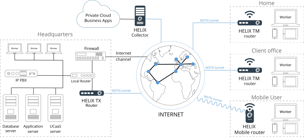
Schematic diagram of the subscriber unit:
The main number of corporate networks are divided into the following types / segments:
1. VOIP-voice traffic, usually implemented according to the scheme: the central office is connected to the operator providing this service and remote units traditionally working through an organized dedicated MPLS or L2TP connections.
2. Video – Video surveillance and security system. Typically completely isolated from the main network of the enterprise, and is controlled by the head of the security service. Technically implemented as a segment working via L2TP connection.
3. Data – Internal workflow with file storage, usually with internet access. Technically, this segment is usually implemented on IPSEC.
4. DMZ – Demilitarized zone is a network segment containing public services and separating them from private ones. For example, a web service can be used as a public service: The server providing it, which is physically located in the local network (Intranet), must respond to any requests from the external network (Internet), while other local resources (for example, file servers, workstations) must be isolated from external access.
5. Internet – Separate corporate Internet channel is usually organized in companies that regulate access to resources of their employees, usually such companies install a firewall or conclude a contract with an operator providing this type of service.
Instead of using several different protocols and technologies from different vendors, the technician gets a multifunctional powerful toolkit, this allows you to implement all modern requirements of the corporate sector on a single technological platform in a single solution, taking into account any number of summarized and reserved channels from different service providers.
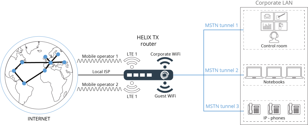
- L2_1 – VOIP
- L2_2 – VIDEO
- L2_3 – DATA
- L2_4 – DMZ
- L2_5 – Internet
In our standard configuration we have added one more segment:
L2-6 – This is a redundant L2 channel made for specific needs of companies (radio communication, ATMs, terminals, stock accounting combinations between warehouses, etc.) or for organizing an additional bundle of VLANs.
External WAN part.
Each subscriber terminal can simultaneously work with several independent Internet/intranet channels using our Multi Service Tunnel Protocol (MSTP) which tunnels with bandwidth summation and/or transport subchannels redundancy.
The principle of operation is described below:
“The MSTP protocol can use any number of different physical communication channels (up to 255), hereinafter referred to as “transport subchannels” to transmit useful data. Subchannels are organized into tx/rx rings (rings) and each ring is assigned a number (ring number – priority). The ring may contain both operating (Online) subchannels, and not working (OffLine). So that the client part of MSTP can inform the collector part of the performance subchannel service packets are used (Service) synchronization.
So only if there is two-way communication (both receiving and transmitting) on the subchannel will the client and the collector mark the subchannel as “working”. If after a certain interval after setting the subchannel in the working mode (online) no synchronization packets were received, the subchannel is marked as not working (offline) and data transmission is terminated…”.
In other words, unlike TCP (which sends a packet to nowhere via a route and waits for confirmation of delivery or resend), MSTP constantly “knows” the actual current state of the route to the destination and always has several alternate routes.
The tunneling module runs in the MTP OS kernel, which provides much better performance than other user-level implementations.
“MSTP allows you to specify for each subchannel the waiting interval for synchronization packets, as well as their number (to protect against a jumping (flapping)) subchannel until the moment when the subchannel is considered to be working. When selecting a subchannel to transmit the next portion of useful data, a search is performed in the nearest (with a minimum number) ring containing working subchannels.
Thus it is possible to organize a multi-level system of reservation of subchannels for useful data transmission in which at first are used fast stable subchannels and only in case of failure of the latter will be involved reserve (in order of decreasing their throughput capacity and quality).
“Also, each of the ring subchannels is divided into two logical subchannels (receive – rx and transmit – tx). Each such subchannel has a number.
This allows asynchronous data transmission (reception by one subchannel and transmission by another.
An example of this situation: one-way satellite Internet, when the reception comes from the satellite and transfer via GPRS/3G/LTE mobile network).
In default operation mode, if there are several working subchannels in the ring, the traffic (packets) for transmission is distributed equally between them.
But it is possible to set criteria for using the bandwidth for subchannels (sub channel rest interval).
Example: one subchannel transmits all packets sent to it, and the other only 33%, yielding the remaining 66% to the next “alive” subchannel in the ring.
Thus traffic going to transmission is distributed in 1/3 ratio.
Just any subchannel (separately for tx and rx) you can set a subchannel for hot backup / mirroring (Hot Backup slave). In this case data packet sent over such subchannel will be cloned and simultaneously transmitted through Hot Backup slave channel. The receiving side will process the first received packet. The rest of its copies will be ignored. This allows you to significantly improve the quality of communication: to eliminate losses, minimize delay variation (Jitter), get a 0-th time of switching to the backup slave”.
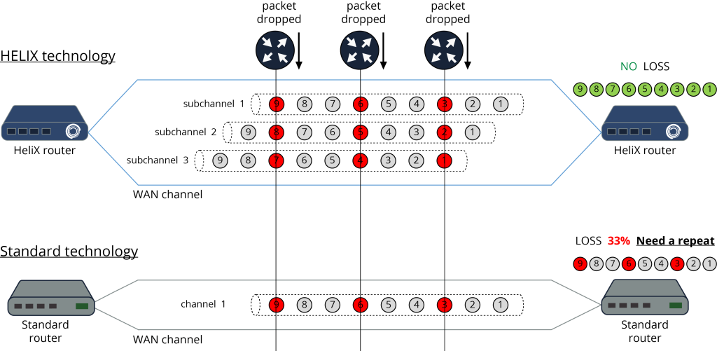
Even when using a lossy channel, the HeliX platform can significantly improve the quality of communication: eliminate losses and minimize jitter.
An example of how to use this feature:
In the normal case, the WAN allows traffic with different priority to be transmitted on different data links (each in its own way). Depending on the priority, the corresponding traffic is transmitted over a better or worse quality channel. But even the best channel does not allow to get rid of losses completely.

MSTNT makes it possible to reduce losses to almost zero when transmitting traffic with high priority.
There are two subchannels: mobile operator1 3G (MO1) and mobile operator2 3G (MO2). Each subchannel gives high jitter and packet loss of 10% For the MO1 subchannel, the MO2 partner is specified. When a payload packet is transmitted through the MO1 subchannel, a copy of the same packet is simultaneously transmitted through the MO2 subchannel. The packet has a unique sequence number so the receiving side can distinguish between two identical packets that come on different subchannels. Thus the receiving side accepts the first arriving packet and ignores all subsequent ones (if they arrived). This significantly reduces losses, since the probability of losing a packet while transmitting on two subchannels, each of which loses 10% of the data is ~ 1% and the jitter of such a subchannel will significantly decrease.

If we add a third subchannel to the scheme (mobile operator3), then the probability of data packet loss is already 0.1%!
That is, from three “bad” channels we gather one ideal! MO1 (main, partner MO2), MO2 (partner MO3).
Also, as it is clear from the described scheme at breakage of one of subchannels the loss of useful data will not happen since the same data, at the same time are transmitted and other two subchannels (partners). Using the described scheme, you can drive a car at a speed of 100 km per hour and the channel will be stable and will not depend on the coverage of the cellular network.
As long as there is coverage of at least one mobile operator communication will work.
By creating a monolithic channel between all networked business resources, the Autonomous System eliminates the possibility of hacker attacks and provides a new level of security quality.
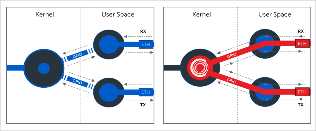
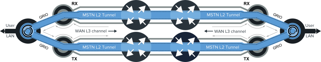
A unique feature of HeliX is that by using public Internet links (Layer L3 – Grey lines) between the two routing endpoints, HeliX transmits MSTN packets on a core-to-core basis at Layer 2 (blue lines), as shown in the figure below. This eliminates the possibility of packet tampering and inspection by conventional routers on the public Internet.
Using custom network indexes and handling MSTN packets inside the kernel makes it impossible for unauthorized IP packets to penetrate HeliX devices, they will be discarded as shown below because they do not have a route to the kernel.
This security feature will help reduce the chance of DDOS attacks.
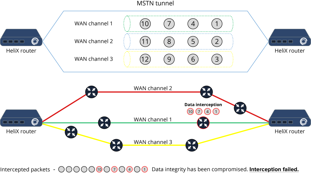
Multiple transport sub-channels give a high degree of security.
Example:
We need to transmit 9000 bytes of data. And we have 3 communication subchannels.
In this case, the first block of 1500 bytes will go in encrypted form through the first subchannel, the second through the second and the third through the third subchannel respectively. If an intruder listens to the traffic on the first subchannel, he will get the first (1…1500 bytes), and the 4th (4501…6000 bytes) data blocks respectively.
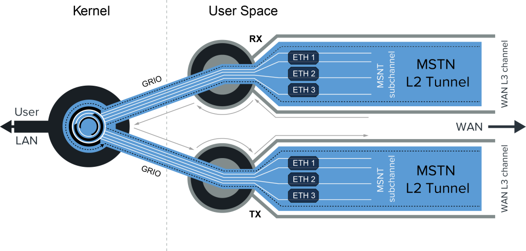
Data packet transmission.
The Autonomous System network consists of a set of edge devices (HeliX Edge) connected to each other via a set of HeliX Collectors (points of presence on the public Internet).
The HeliX platform uses L2 tunnels between HeliX routing points (Edge-to-Collector and Collector-to-Collector), thereby isolating data transport as an overlay on top of the public Internet.
A proprietary packet fragmentation algorithm reduces routing information and fills the MSTN packet as much as possible with useful data, as shown in the figure below. Fragmentation data is transmitted in the service fields of the MSTP tunnel header, of which the transit routers know nothing and can not detect the presence of fragmented traffic and, therefore, prevent its distribution.
The protection of data transmitted in HeliX L2 tunnels can be strengthened by encrypting the data with any encryption method chosen by the client.
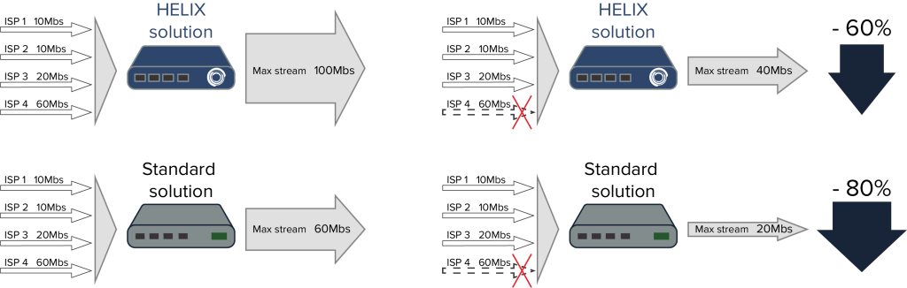
Summation Functions.
A unique feature that allows for efficient use of bandwidth is the “summation” feature, which differs from the usual “bonding” and “aggregation”.
As shown in the figure, unlike existing tunneling systems, the Autonomous System provides the ability for any subscriber terminal to aggregate multiple physical links in bandwidth summation mode and in redundancy mode (in hot or cold redundancy mode). Such channel bandwidth summation guarantees preservation of packet sequence, can transparently summarize transport channels and protect data packets when they are transmitted over an unprotected Internet network.
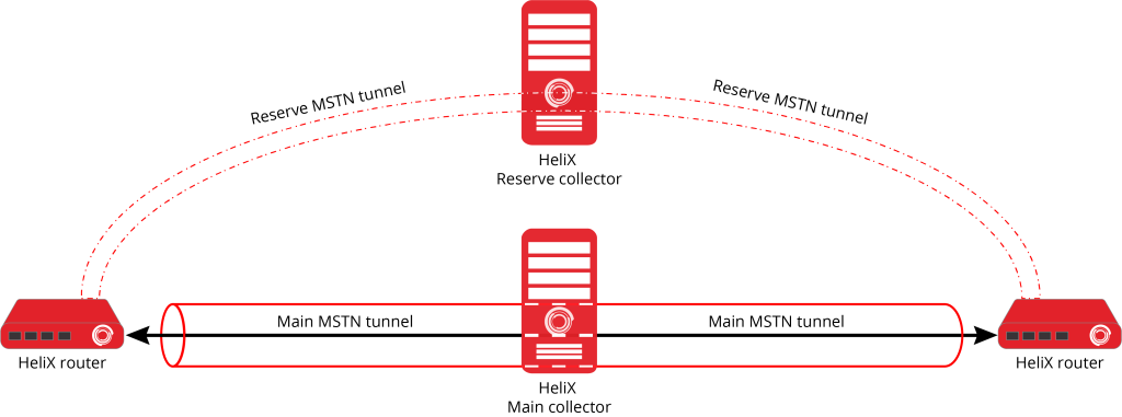
Redundancy and fault tolerance.
The HeliX networking platform includes several redundancy and fault tolerance features in its systems and processes. The following is a brief description of the key features. HeliX provides fault-tolerant routing for client network topologies.
The HeliX networking platform allows you to create redundant collectors. The primary and backup collector can be geographically distributed and even be located on different continents. If the primary collector fails, the system automatically and instantly switches to the backup collector.
Emergency Operation.
When a failure occurs on a lower-layer collector, the system automatically redirects traffic from the edge routers to the upper-layer collector, as shown in the figure below. In this way, HeliX can provide enhanced access with improved bandwidth.
HeliX emergency switching does not interrupt the current session and ensures connection stability and service continuity.
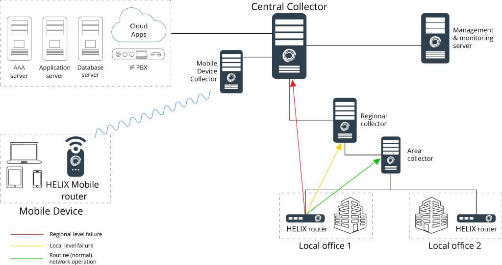
Automatically switches the subscriber’s session to another HELIX collector if the connection is lost.
- Connection of the local office to the branch office in normal mode (green line).
- Automatically switches to an alternate route (yellow line) if the connection to the branch office is broken.
- Connection of the local office directly to the head office, in case the connection to the branch office and the regional office is interrupted (red line).
- Emergency switching does not lead to interruption of the current session, and provides a stable connection and continuity of service.
In combination with hot redundancy and protection against data corruption in case of equipment or channel failure, the AS allows you to deliver packets in the shortest available way. At the same time, the monitoring system will immediately notify the personnel responsible for the problematic network segment with the data collected about the failure.